7.3.2. Rotated Surface Code Examples
Simple noiseless memory experiment
We provide a simple example of a noiseless memory experiment using a distance-3 rotated surface code. The experiment initializes the logical qubit in different states, performs syndrome measurements, and finally measures the logical qubit. The final circuits are then simulated using Stim to validate that the logical qubit behaves as expected.
# Initialize block
rsc_block_1 = RotatedSurfaceCode.create(3, 3, lattice, unique_label="rsc_block_1")

states_list = ["1", "0", "+", "-"]
logicals_names = ["Z_L", "Z_L", "X_L", "X_L"]

# Create four circuits, each with a different logical state initialized
interpreted_circ_list = []
for state in states_list:
    operations = (
        (   # Encode pt1: Reset all data qubits
            ResetAllDataQubits(rsc_block_1.unique_label, state=state),
        ),
        (   # Encode pt2: Encode data qubits via measurements
            MeasureBlockSyndromes(rsc_block_1.unique_label, n_cycles=1),
        ),
        (   # Syndromes: Information collection
            # (not technically necessary in a noiseless experiment)
            MeasureBlockSyndromes(rsc_block_1.unique_label, n_cycles=2),
        ),
        (   # Measure logicals
            MeasureLogicalZ(rsc_block_1.unique_label)
            if state in ["0", "1"]
            else MeasureLogicalX(rsc_block_1.unique_label),
        ),
    )

    eka_obj = Eka(lattice, blocks=[rsc_block_1], operations=operations)
    interpreted = interpret_eka(eka_obj)

    interpreted_circ_list.append(interpreted)

from loom.executor import EkaToStimConverter
import numpy as np

# STIM settings
stim_nsamples = 1000

converter = EkaToStimConverter()
for index, interpreted in enumerate(interpreted_circ_list):
    # Convert interpreted Eka circuit to Stim circuit
    stim_circ = converter.convert(interpreted)

    # Sample the Stim circuit
    sampler = stim_circ.compile_sampler()
    samples = sampler.sample(shots=stim_nsamples)

    # Get logical counts
    output = {}
    for stim_obs in range(1, stim_circ.num_observables + 1):
        obs_instr = stim_circ[-stim_obs]
        meas_indices = [rec.value for rec in obs_instr.targets_copy()]
        obs_samples = np.bitwise_xor.reduce(samples[:, meas_indices], axis=1)

        # Get counts
        unique_el, counts = np.unique(obs_samples, return_counts=True)
        output[stim_obs] = {"0": 0, "1": 0}

        for i in range(len(unique_el)):
            output[stim_obs][str(int(unique_el[i]))] = counts[i].item()

    # Print output for each circuit
    for key, value in output.items():
        print(f"Circuit{index + 1} {logicals_names[index]}: {value}")

    # Get detector flips
    det_samples_list = []
    for stim_det in range(1, stim_circ.num_detectors + 1):
        det_instr = stim_circ[-stim_det - stim_circ.num_observables]
        meas_indices = [rec.value for rec in det_instr.targets_copy()]
        det_samples = np.bitwise_xor.reduce(samples[:, meas_indices], axis=1)

        det_samples_list.append(sum(det_samples))

    # Print unique detector flips
    print("Detector flips: ", sum(det_samples_list))
    print()

## Expected output:
# Circuit1 Z_L: {'0': 0, '1': 1000}
# Detector flips:  0
#
# Circuit2 Z_L: {'0': 1000, '1': 0}
# Detector flips:  0
#
# Circuit3 X_L: {'0': 1000, '1': 0}
# Detector flips:  0
#
# Circuit4 X_L: {'0': 0, '1': 1000}
# Detector flips:  0
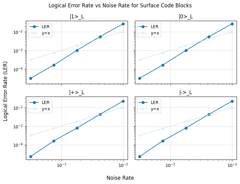
Simple noisy memory experiment
We adapt the Eka circuit from the previous section to provide an example of a noisy memory experiment. We will apply varying levels of noise to the circuit using Stim to validate that the logical qubit is able to correct errors up to its threshold. We will use the PyMatching package to decode the detector outcomes, and use MatPlotLib to plot the logical error rate as a function of physical error rate.
from loom.executor import noise_annotated_stim_circuit
import pymatching as pym

stim_nsamples = 1_000_000
noise_rates = [10 ** (i) for i in np.linspace(-3.5, -2, 5)]

converter = EkaToStimConverter()

circuit_lers_list = [[], [], [], []]
for cir_index, interpreted in enumerate(interpreted_circ_list):
    stim_circ = converter.convert(interpreted, with_ticks=True)

    for noise in noise_rates:
        stim_circ_noise = noise_annotated_stim_circuit(stim_circ, after_clifford_depolarization=noise)

        # Create detector error model and matching graph
        dem = stim_circ_noise.detector_error_model(decompose_errors=True)
        matching_graph = pym.Matching.from_detector_error_model(dem)

        # Sample the Stim circuit
        det_sampler = stim_circ_noise.compile_detector_sampler()
        samples, actual_log = det_sampler.sample(shots=stim_nsamples, separate_observables=True)
        predicted_log = matching_graph.decode_batch(samples)

        ler_stim = sum(pred != act for pred, act in zip(predicted_log, actual_log)) / len(
            actual_log
        )
        circuit_lers_list[cir_index].append(ler_stim)

## Plot results using MatPlotLib
import matplotlib.pyplot as plt

fig, ax = plt.subplots(nrows=2, ncols=2, sharex=True, sharey=True, figsize=(8, 6))
fig.suptitle("Logical Error Rate vs Noise Rate for Surface Code Blocks")
fig.supxlabel("Noise Rate")
fig.supylabel("Logical Error Rate (LER)")

for i, row in enumerate(ax):
    for j, col in enumerate(row):
        col.plot(
            noise_rates,
            circuit_lers_list[i],
            marker="o",
            linestyle="-",
            label="LER",
        )
        col.plot(
            noise_rates,
            noise_rates,
            marker="x",
            linestyle="-",
            label="y=x",
            color="lightblue",
            alpha=0.5,
        )

        col.set_title(f"|{states_list[2 * i + j]}>_L")

        col.set_xscale("log")
        col.set_yscale("log")

        col.grid(linestyle="--", linewidth=0.5)

        col.legend()

fig.tight_layout()
plt.show()
Simple noiseless bell state experiment
We provide a simple example of how to initialize a logical bell state using lattice surgery operations on a distance-3 rotated surface code block. The experiment grows and splits the block into two while performing syndrome measurements, before finally measuring the logical qubits in the X and Z basis. The final circuits are then simulated using Stim to validate that the logical qubits behave as expected.
from loom.eka.utilities import Direction, Orientation

# Create a rotated surface code block
rsc_block_1 = RotatedSurfaceCode.create(3, 3, lattice,
                                        unique_label="rsc_block_1")

# Add some operations on the blocks
logicals_names = ["XX_L", "ZZ_L"]

# Create two circuits, each measuring a different logical operator
interpreted_circ_list = []
for logicals in logicals_names:
    operations = (
        (   # Encode pt1: Reset all data qubits
            ResetAllDataQubits(rsc_block_1.unique_label, state="+"),
        ),
        (   # Encode pt2: Encode data qubits via measurements
            MeasureBlockSyndromes(rsc_block_1.unique_label, n_cycles=1),
        ),
        (   # Lengthen the block along X boundary
            Grow(rsc_block_1.unique_label, Direction.RIGHT, length=4),
        ),
        (   # Syndromes: Information collection
            MeasureBlockSyndromes(rsc_block_1.unique_label, n_cycles=1),
        ),
        (   # Split the block into two d=3 blocks
            Split(rsc_block_1.unique_label, ("rsc_block_1_a", "rsc_block_1_b"),
                Orientation.VERTICAL, split_position=3),
        ),
        (   # Syndromes: Information collection
            MeasureBlockSyndromes("rsc_block_1_a", n_cycles=1),
            MeasureBlockSyndromes("rsc_block_1_b", n_cycles=1),
        ),
        (   # Measure logicals
            (MeasureLogicalX("rsc_block_1_a"), MeasureLogicalX("rsc_block_1_b"),)
            if logicals == "XX_L"
            else (MeasureLogicalZ("rsc_block_1_a"), MeasureLogicalZ("rsc_block_1_b"),)
        )
    )

    eka_obj = Eka(lattice, blocks=[rsc_block_1], operations=operations)
    interpreted = interpret_eka(eka_obj)

    interpreted_circ_list.append(interpreted)

# STIM settings
stim_nsamples = 1000

converter = EkaCircuitToStimConverter()
for index, interpreted in enumerate(interpreted_circ_list):
    stim_circ = converter.convert(interpreted)

    # Sample the Stim circuit
    sampler = stim_circ.compile_sampler()
    samples = sampler.sample(shots=stim_nsamples)

    # Get counts
    obs_samples = []
    for sample_id in 2, 1:
        obs_instr = stim_circ[-sample_id]
        meas_indices = [rec.value for rec in obs_instr.targets_copy()]
        obs_samples.append(np.bitwise_xor.reduce(samples[:, meas_indices], axis=1))

    # Combine observables
    samp = np.bitwise_xor.reduce(obs_samples, axis=0)

    # Get logical counts
    unique_el, counts = np.unique(samp, return_counts=True)

    output = {"0": 0, "1": 0}
    for i in range(len(unique_el)):
        output[str(int(unique_el[i]))] = counts[i].item()

    # Print output for each circuit
    print(f"Circuit{index + 1} {logicals_names[index]}: {output}")

    # Get detector flips
    det_samples_list = []
    for stim_det in range(1, stim_circ.num_detectors + 1):
        det_instr = stim_circ[-stim_det - stim_circ.num_observables]
        meas_indices = [rec.value for rec in det_instr.targets_copy()]
        det_samples = np.bitwise_xor.reduce(samples[:, meas_indices], axis=1)

        det_samples_list.append(sum(det_samples))

    # Print unique detector flips
    print("Detector flips: ", sum(det_samples_list))
    print()

## Expected output:
# Circuit1 XX_L: {'0': 1000, '1': 0}
# Detector flips:  0

# Circuit2 ZZ_L: {'0': 1000, '1': 0}
# Detector flips:  0